Introduction to C4 Diagramming

Scenarios
Scenario 1: Imagine you are at the airport in a foreign country and about to fly to your home country.A stranger sits next to you, greets you and ask you where are you from. What will be your response?
Scenario 2: Imagine you are at the domestic terminal in your home country, and you are about to fly to another city. A stranger greets you and ask you where are you from. What will be your response?
Scenario 3: You are in a coffee shop at local shopping centre and stranger asks you where are you from, what will be your response?
Do you have different answers in the 3 scenarios? If so why?
 Credit rgbstock
If I had to respond
I’m from a village called Mabeskraal, classified under Rusternburg town/district in South Africa. My response in 3 scenarios:
- In a foreign country : I’m from South Africa
- In my home country: I’m from Rusternburg
- At local shopping mall: I’m from Mabeskraal
Answers are different because "it depends" on where I am are at the particular point, and who's asking. In a case where the stranger is familiar with South Africa, dialog might go like this:
- Stranger: Where in South Africa?
- Me: In Rusternburg (Zooming 1 level down)
- Stranger: Oh I’ve been to Rusternburg, where exactly?
- Me: In a village called Mabeskraal (Zooming another level down)
C4 Modelling
How does C4 fit in all of this? It is all about the ability to zoom in and out "depending" on where you are and the people you are talking to.
According to C4Model.com, C4 is a way of creating maps of your software at various levels of detail just like what you would do on google maps. In google maps, you can zoom in & out to different levels of detail.
C4 model, inspired by UML and 4+1 model , is a simplified and practical way of describing systems from different levels of abstractions.
C4 Core Diagrams
Core diagrams provides a static view of a single software system. Core diagrams includes context, container, component and code.
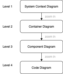
The next sections discusses each diagram in detail.
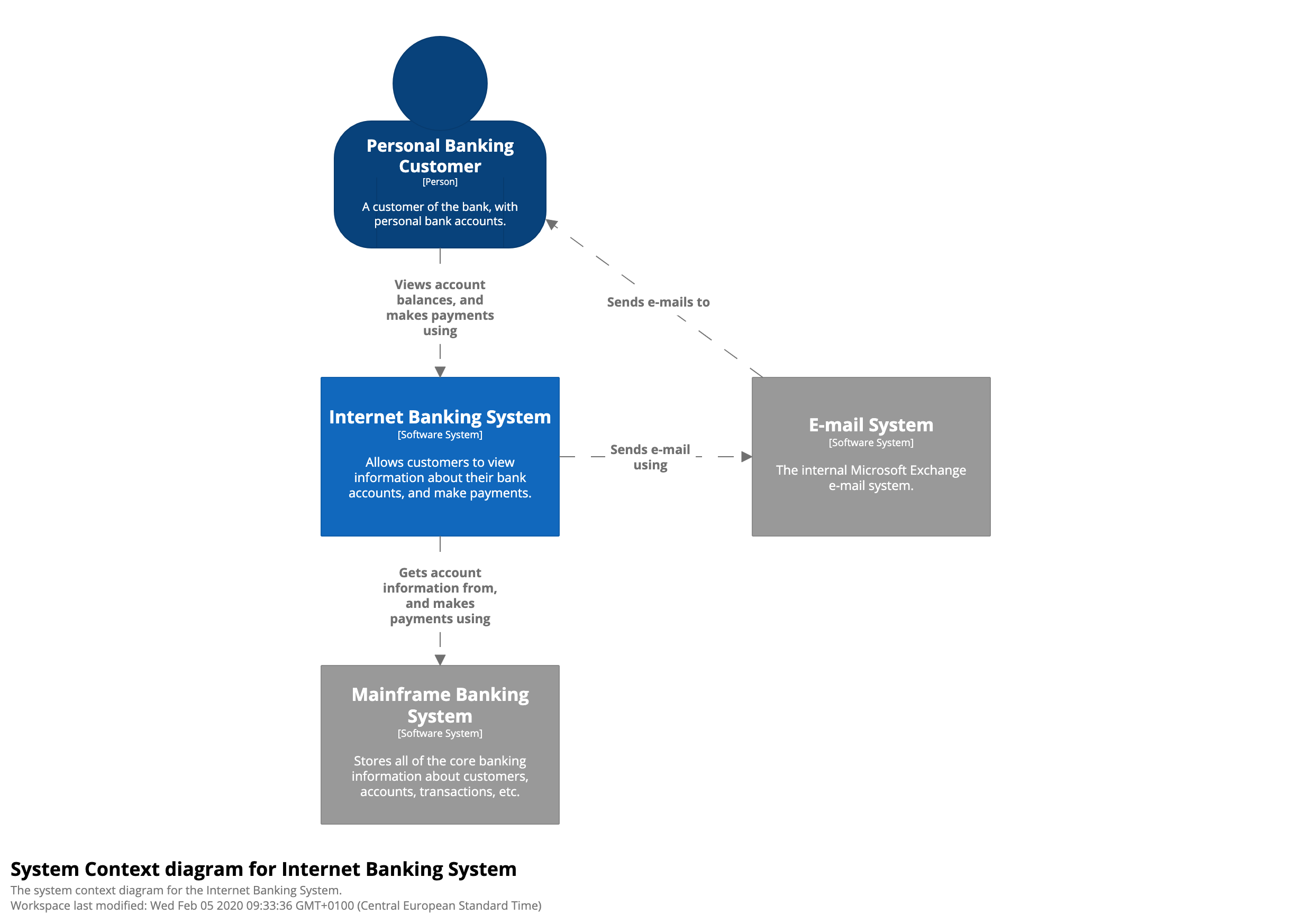
1: System Context Diagram
Context diagram allows you to take a step back and see the bigger picture. It highlights the system we focusing on(hence the color blue), and the other systems and actors it integrates with. Each connection or relationship to actors or systems must have the purpose.
The diagram is what we use at the beginning of the story before zooming into details. The diagram is good for both technical and non-technical people, but I’ve seen more value when presented to non-technical people.
It is important not to add technical details or the components that makes up the system in this diagram. No need to mention Azure, AWS, API, Database details etc. Those details are mentioned as we zoom into the next level of details, the container diagram.
 Credit c4model.com
Because c4 represents a static view of a single software system, the "system in focus" is always blue. Other systems are gray in color because they are not the "single software system" we focusing on. If we need to focus on them, we need to create separate diagrams for them.
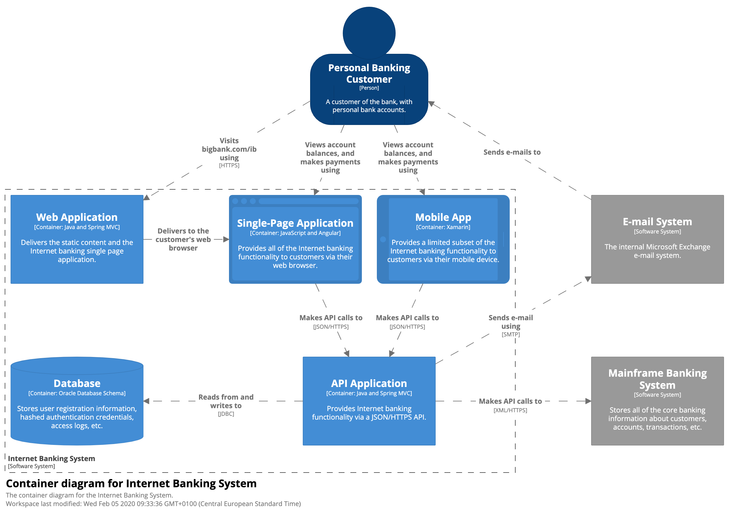
2: Container Diagram
A container diagram is a high-level technology focused diagram that zooms a level down into the focus system (Blue Box) highlighted in System Context Diagram.
According to C4Model.com, a container represent an application or data store. It is a piece of software that we deploy in order for the whole system to work. Example of a container includes web app, mobile app, lamda function, azure functions, database, blob storage etc.
Container != Docker Container (!= not equals to) Container does not represent a dll/jar, its represent application which can be collections of dlls or Jars
We can add technical details to containers like React Native Mobile App, Azure Function, Mongo DB etc. The diagram does not highlight any network related concepts like fail over, clustering, deployment scenarios etc.
 Credit c4model.com
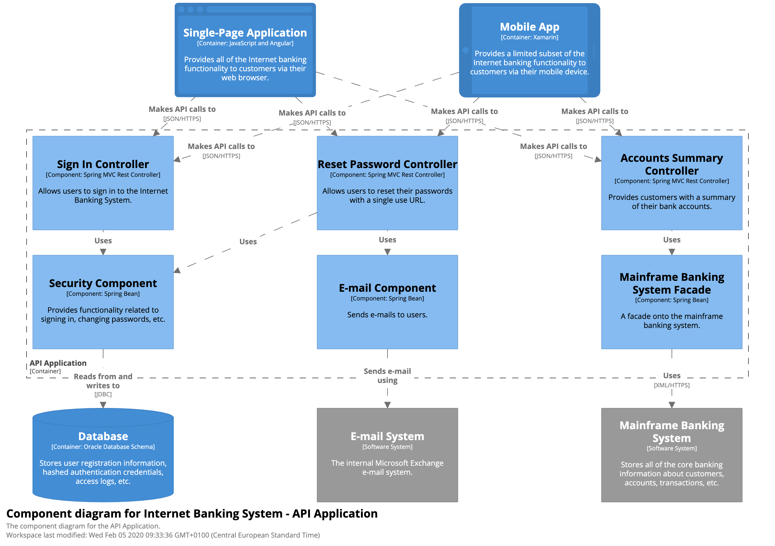
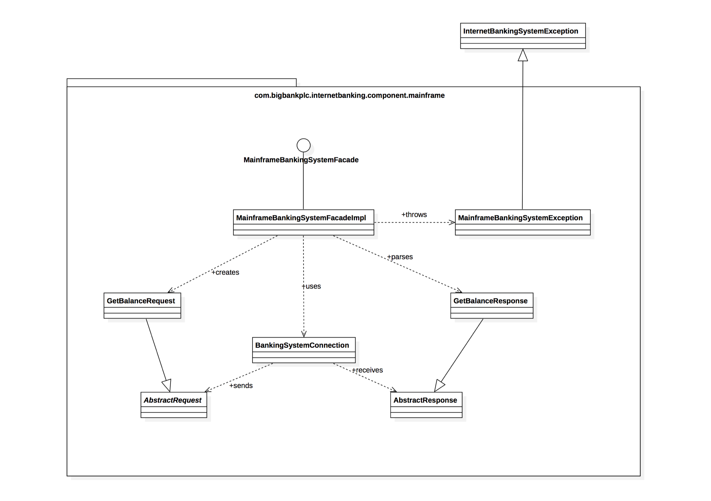
3: Component Diagram
Component diagram is a level 3 diagram that drills down into a a container, highlighting the building blocks of a container.
A component is a collection of implementation classes behind an interface.
Important to note: Components are not separate deployable pieces of software, container is.
I'm not a big fan of component diagram and I have not seen the need for them. It’s not recommended to create them unless they add value to you and your team. If anyone is interested in this level of details, it’s better they jump into the repo and see it fresh.
 Credit c4model.com
4: Code
It is the last level of C4 model where yo zoom into each component to show how it’s implemented as code.
It is not recommended to create this model since some IDE can automatically generate them from code.
 Credit c4model.com
Supplementary Diagrams
Samples of supplementary diagrams mentioned below are available on C4Model.com
System Landscape Diagram
System landscape Diagram is a context diagram without focus in a single system.
In some cases especially in projects, we need to present multiple applications in a single picture. Because C4 Core Diagrams focuses on a a static view of a single system, it might not be relevant.
In my experience, this is one of the simple pictures to design provided you have core diagrams of all application within your organization.
Dynamic Diagram
Just like on UML communication/collaboration diagram, it’s a diagram that shows sequence or numbered interactions between actors and applications.
I find it useful to describe simple scenarios. Where lots of containers are involved, traditional sequence diagram is simpler to understand.
Deployment Diagram
Shows how systems and containers are mapped to infrastructure. It’s based on UML Deployment diagram.
This is where we show networks, load balancers, firewalls etc.
Guidelines when creating c4 diagrams
According to C4Model.com,
- Each diagram should have title describing diagram type and scope (e.g. Context diagram of Travel Sko).
- Each diagram should have a legend.
- Acronyms and abbreviations should be understandable, otherwise avoid them.
- Every container should have technology explicitly specified. (e.g Azure function, React Web app)
- Every relationship should be label with direction and intent
- Diagrams should not be stale. I prefer to only create Context and Container diagram because their rate of change is very low and easy to keep them fresh.
Conclusion
Some of the reasons why I like C4 diagramming/modelling
- It is a simplified UML.
- It’s practical, easy to understand.
- Promote distributed design within the organizations.
- Most important, it clarifies the System Boundary, which can be a struggle as highlighted on understanding boundaries post.
The first 2 diagrams (Context and Container) are key and can bring clarity and alignment needed through out the organization. If each system in the organization has this 2 diagrams (fresh not stale), there would not be a need to have meetings & meetings where architects or engineers explains details (structure, integration, relationships, deployed containers) of the system they look after. Most importantly, some conversations would not need architect or engineer to be present.
It is important to note that C4 does not cover all architecture artifacts. Missing link:
- Sequence Diagram: Dynamic diagram can replace a sequence diagram but lots of lines/activities will complicate it. I still feel there’s a room for sequence and I’ll cover it in my next post.
- Business processes, workflows, state machines, domain models,
- Data models
As we close, let’s marry our scenarios to c4
- In a foreign country : I’m from South Africa = Context Diagram
- In my home country: I’m from Rusternburg = Container Diagram
- At local shopping mall: I’m from Mabeskraal = Component Diagram